
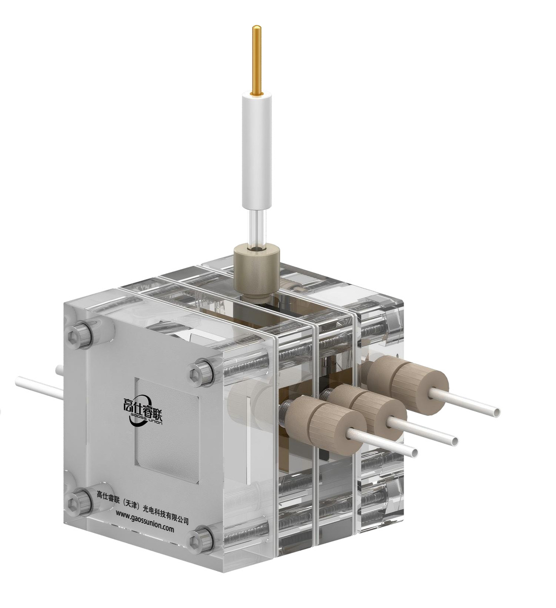
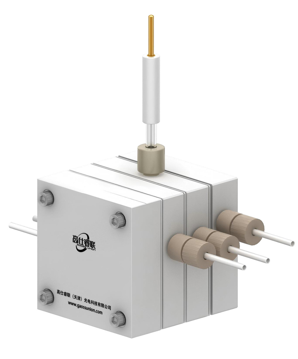
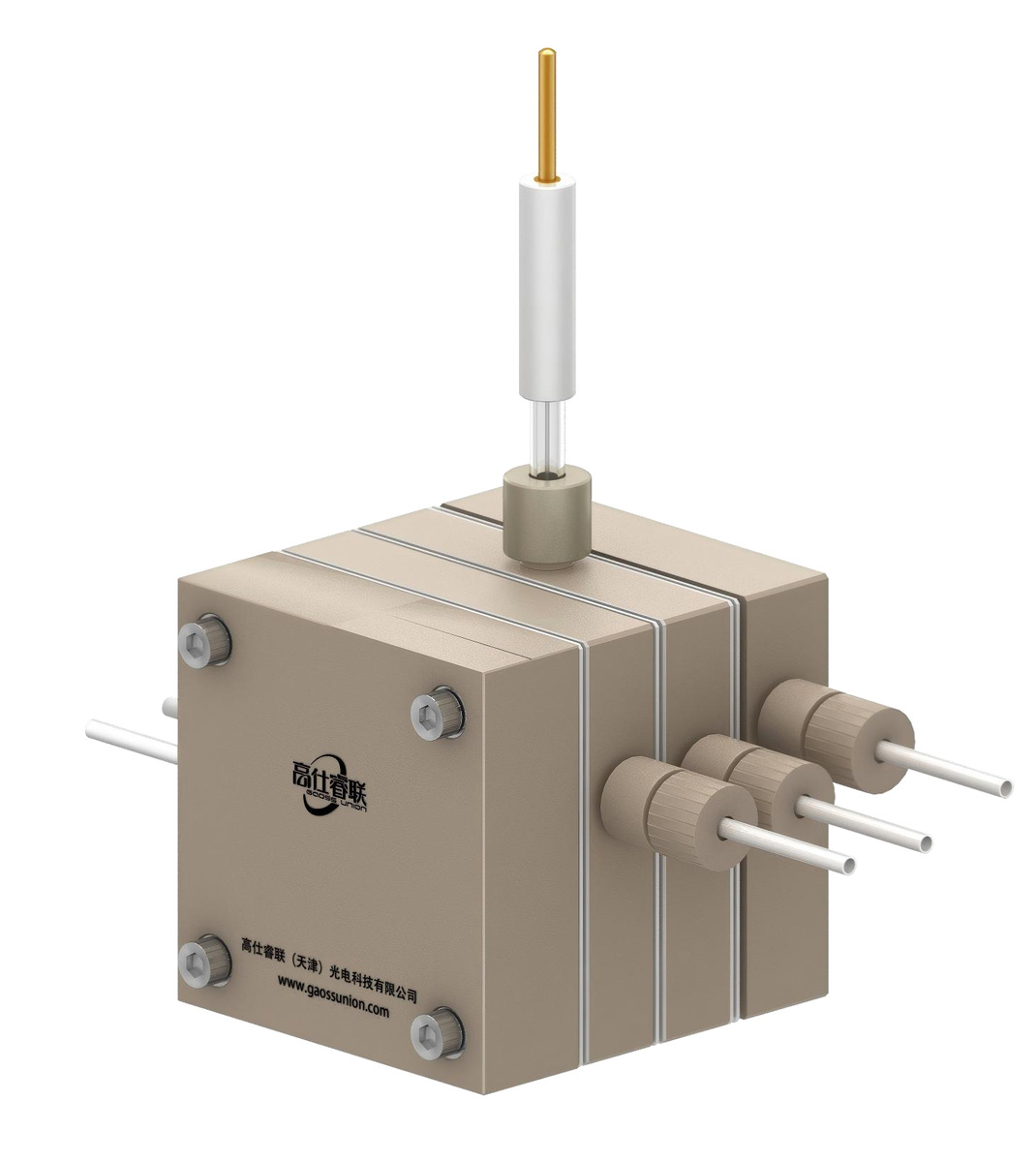
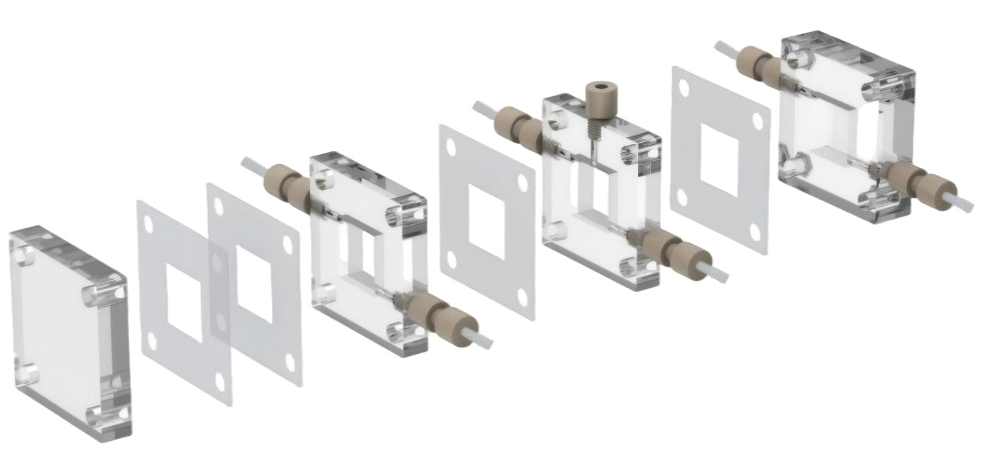
Product overview
The CP10 / CP20 range uses separate flow paths for gas and electrolyte. The catalog shows gas entering from the top and liquid entering from the bottom, with outlets in the opposite direction. Choose the channel geometry and wetted material around the chemistry, then confirm the selected model and connection scope with SSI.
Specifications & ordering details
Use these parameters to define your requirement. The quotation confirms the exact supplied specification.
| Material / system | PMMA, PTFE or PEEK options |
|---|---|
| Catalog model range | CP10 / CP20 |
| Standard channel sizes | 10 × 10 mm or 20 × 20 mm; confirm selected model |
| Anode-to-cathode distance | 20 mm |
| Body material options | PMMA, PTFE or PEEK |
| Active area and flow-field design | Specify with your requirement. |
| Plate / current-collector materials | Specify with your requirement. |
| Connections and included accessories | Specify with your requirement. |
Research applications
- Gas-diffusion flow experiments
- Flow-path development
- Electrochemical catalyst studies
Before you order
- State the required channel size and body material.
- Provide gas and liquid flow requirements.
- Confirm the membrane, electrodes and fittings included in the assembly.
Product documents
View the source catalog for this offering. Share your grade, model and application to request the relevant specification or material documentation.
View Electrochemistry, Flow & MEA Systems — page 37 ↗Download PDFSelection questions
What should a custom enquiry include?
For CP10 / CP20 Gas-Diffusion Flow Cell, provide the active area, sample or electrode geometry, materials, interfaces and the operating conditions. Include drawings and identify every component in the assembly scope.
Are electrodes, membranes and accessories included?
Specify the parts required. Hardware, membranes, electrodes, gaskets, fittings and instruments should be identified separately in the quotation.
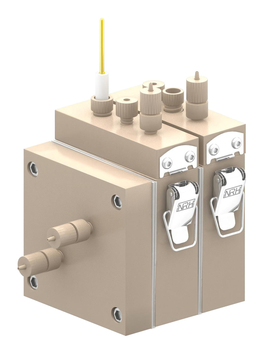 101014 Entry-Level Gas-Diffusion Cell
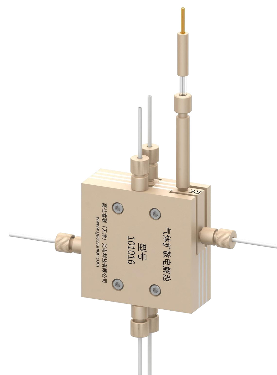 101016 Three-Chamber Gas-Diffusion Cell
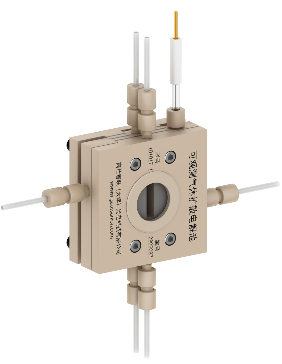
 101017-1 Windowed Gas-Diffusion Cell
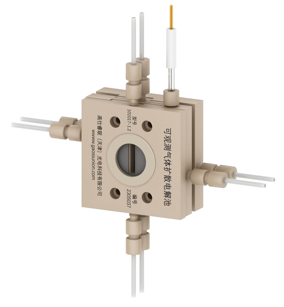
 101017-1.2 Windowed Gas-Diffusion Cell